Universal wall mounted touchscreen bezel
After moving house, I no longer had my elaborate DIY home-automation setup running. I no longer had my touchscreens in place of lightswitches as detailed here.
I wanted to install the touchscreens again, but this time I desired more control over the hardware. Whilst the Fire TV tablets were functional, and the displays were high quality, I didn’t like the fact that they were running the rather locked-down FireOS and contained a volatile lithium-ion battery.
I settled on using an official Raspberry Pi display in combination with a Raspberry Pi 3B as it is the most open, widely supported platform with long-term availability. This is at the expense of screen resolution and viewing angle, mind you.
I had a lot of interest in the last design, so I re-wrote the bezel code (in OpenSCAD) as detailed in the last blog post to make it easier to adapt to any display. Here’s the result!
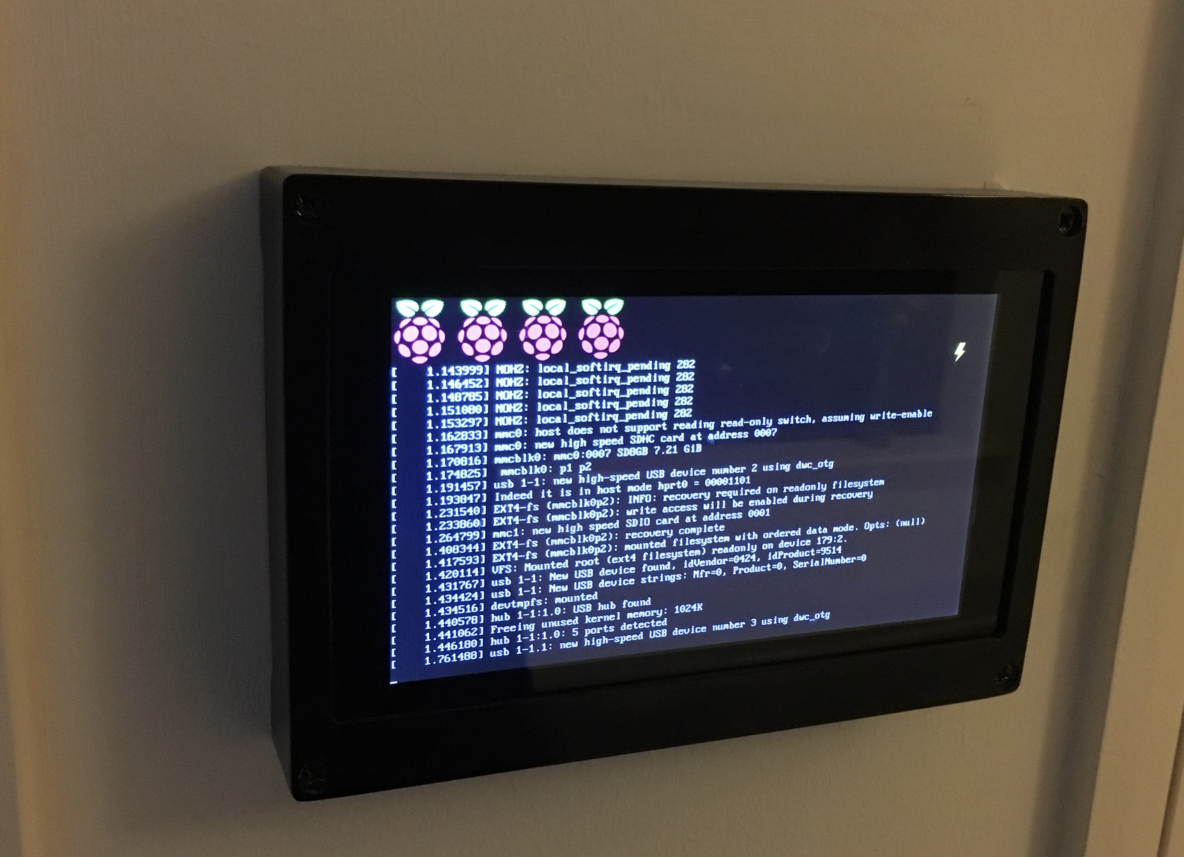
As you can see there is an issue with the power supply to the Pi. It only started doing this a month or so after installation. I suspect the PoE adapter.
The 3d model in OpenSCAD:
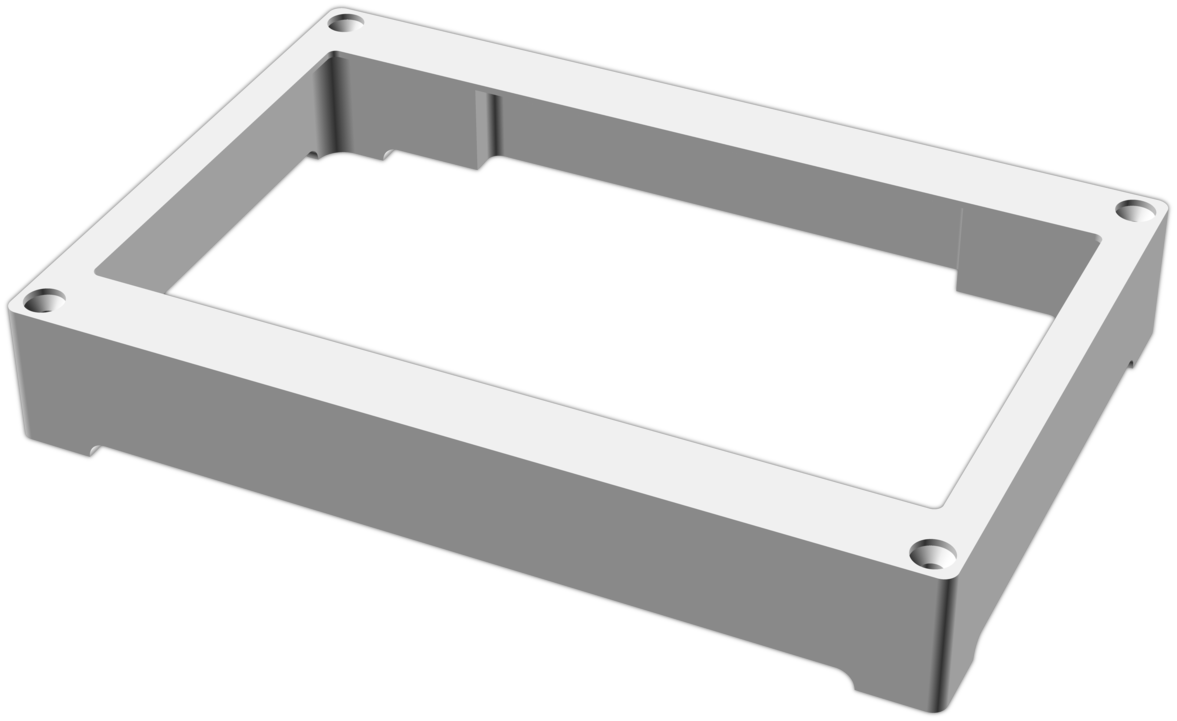
Around the edges I’ve added automatically sized vents – they are now adequate to provide sufficient cooling to prevent overheating during the summer for the Pi 3. They also help to make the unit look slimmer.
The screw holes are countersunk to accept standard 4x25mm woodscrews, allowing installation with wallplugs. The recommended mounting method is to press the bezel against the wall, level it, drill 4mm pilot holes directly through the holes, and then ream out the holes in the wall with a 6mm bit before inserting wall plugs.
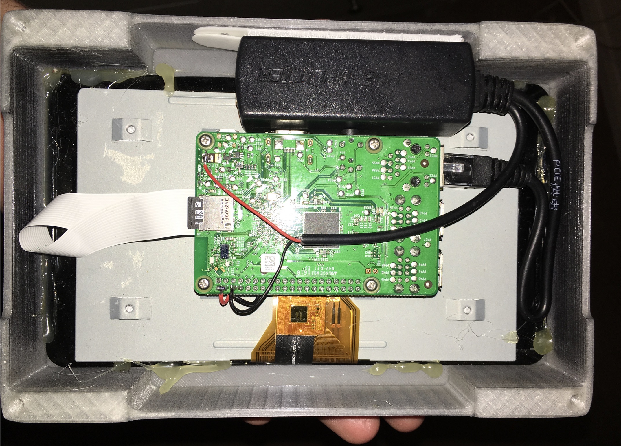
Behind, I’ve managed to fit the Pi 3 in reverse orientation with a PoE adapter to power both the display and the Pi:
I’ve decided to open source this design, complete with the source and a pre-built STL: https://github.com/naggie/lcd-wallmount. If you use it, please let me know!
Update: after a few weeks of use, the power warning indicator was persistently visible. I’m not sure why this appeared after some time, but I managed to fix it.
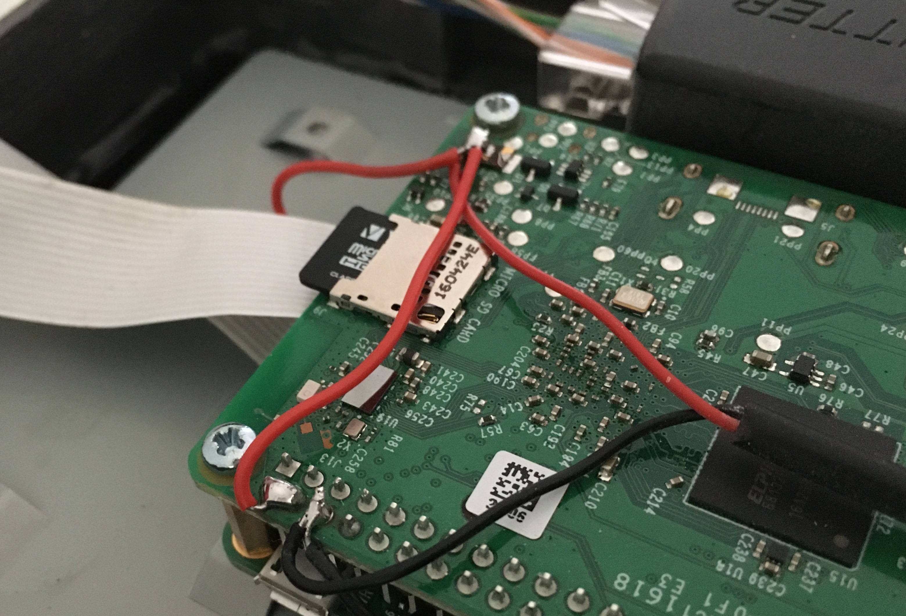
Measuring with the multimeter, I read 5.1v from the PoE adapter even under heavy load. This suggested that the power supply was fine, as it’s within the USB spec of 4.5v to 5.5v. Measuring at the GPIO header, the voltage was under-spec at times. I measured a voltage between the fuse and the GPIO header along a power trace – this was due to IR drop and was the culprit. Jumping across with some wire prevented this drop and resolved the issue:
Thanks for reading! If you have comments or like this article, please post or upvote it on Hacker news, Twitter, Hackaday, Lobste.rs, Reddit and/or LinkedIn.
Please email me with any corrections or feedback.