Pushing OpenSCAD to the max
OpenSCAD is an open-source CSG based script-only CAD package. As it’s script-based, it’s fantastic for parametric design and the files can be version controlled just like a software project. It’s popular within the 3D-printing community due to its ability to produce STL files.1
Despite being actively developed, broadly used and powerful2; there are many shortcomings which make it difficult or sometimes impossible to use outside of 3D printing.
I’ve used OpenSCAD3 to produce a few things that were sent to be manufactured; this article shows how I adapt its output capabilities and how I approach a design. This allows to produce files that can be used for sheet metal cutting, machining and renders – while allowing for complex designs without creating a mess.
General approach
In this section I’ll detail a few hints I’ve thought about when producing a lot of designs for various things around the house.
Work in 2d first
In OpenSCAD, if your design can be described as one or more 2D shapes that can be extruded (etc) into a 3D features, it’s much better to start them in 2D first – here’s why:
- No z-fighting, so no marginal adjustments to make sure you avoid co-incident planes
- The offset transformation allows easy rounding, filleting and shelling if combined with separate 3D operations. See the later section..
- It’s useful to re-use the 2D objects again for things like holes, supports, etc
- The 2D parts are fast to render!
Internal / external chamfers / fillets
OpenSCAD can’t currently chamfer or fillet 3D objects. There have been user-land solutions however, but with caveats. For instance https://github.com/openscad/openscad/issues/884
It’s easy, though, to chamfer/fillet extrusions in negative and positive space. This is often performed manually using a hull between circles, for example:
| |
Note the manual arithmetic required to retain correct dimensions. Using offset, twice, can simplify this:
| |
As stress concentrates at sharp changes in geometry, adding a chamfer or fillet can be the difference between an extremely strong part and one that fails straight away.
Difference of difference
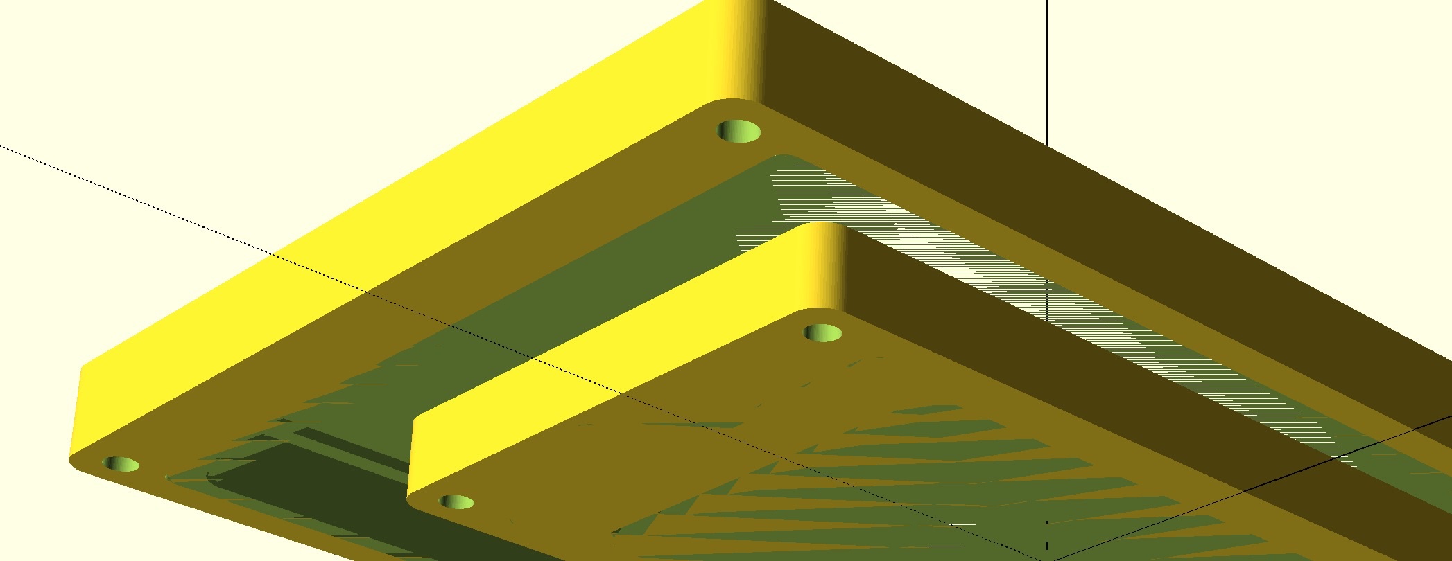
Sometimes when describing negative space it’s useful to do a difference of a difference. Here, for a conduit light adapter design, I used a difference of a difference to effectively subtract a space at an angle, complete with mounting fixtures.
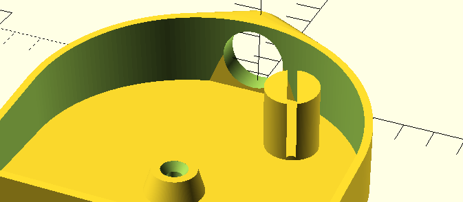
This allows the fixtures to be described negatively and in the same frame of reference as the main subtraction. As a result, it’s not necessary to do potentially complex trigonometry to position the fixtures.
The only caveats are the artefacts in the GL based preview, and the rendering time if you’ve used a lot of curves.
Organise larger projects using directories and files
Large projects can be difficult to manage. It’s all to easy to end up with a monolithic file with a lot of hardcoded variables and confusing modelling. For my speaker design and my 2u rack design, I adopted the following convention; I think it has helped greatly:
| File/directory | Description |
|---|---|
main.scad | Includes everything in include/, and defines main parameters |
Makefile | Make targets to render everything discussed in this document |
dist/ | All build products produced by the makefile in the mirror image of the source go here |
etc/ | Reference materials, datasheets, simulations, etc |
RTM/ | Any files you’ve released to manufacturing, by revision number |
include/ | The main bulk of the project separated into main parts. Included by main.scad |
jigs/ | Templates and fixtures to aid manufacturing |
lib/ | Parts related to the project usable elsewhere. For instance, connector models or tools |
parts/ | Parts manufactured separately. Includes main.scad and instantiates modules from include/ |
views/ | Assemblies and individual parts for 3d rendering |
Reduce Z fighting
To reduce Z-fighting, which is the result of co-incident (enough) planes, it’s necessary to make objects that would otherwise have co-incident planes translate slightly; just apply a translation of 0.001 or so in a direction normal to the planes, taking care to do to this in increments for multiple instances.4 0.001 is usually enough.
In addition, working in 2D until 3D is needed helps, see the section earlier in this article.
Use the cheatsheet
The official cheatsheet is an excellent reference. Despite having used OpenSCAD for years, I still refer to it when doing something slightly odd.
Post-processing output
For 3D Renderings
OpenSCAD can output an image in PNG format. It works fairly well, however the images are not anti-aliased – so they look jagged, they’re yellow by default and may have rendering artefacts.
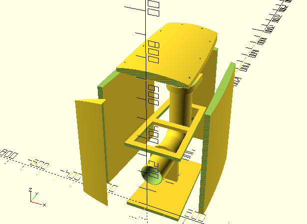
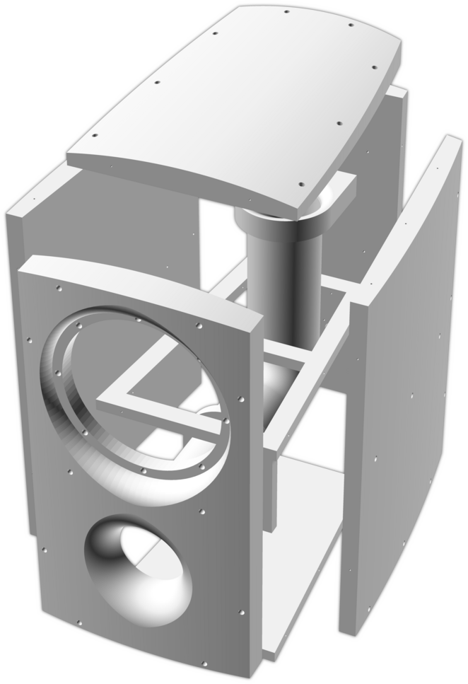
For a recent project (a curvy bass-reflex subwoofer) I wanted to make a rendering of each part as neatly as possible, composited into a contact sheet; much like a Lego catalogue would show the parts and assemblies.
To achieve this quality of render, we need to work around these shortcomings:
- The default scad PNG renderer may produce artefacts such as incorrect boolean rendering and z-fighting
- The renderer does not support anti-aliasing, so there are jagged edges
- The background is not transparent
- Rendered STLs can be non-manifold despite care. (Note, this is not necessarily a problem for rendering PNGs)
They can be worked around by, respectively,
- Rendering to STL first and then rendering that STL via import
- Rendering at 8x resolution and downscaling with an interpolation algorithm such as Lancsoz (using ImageMagick)
- Picking a built-in palette with a background that does not occur in the foreground and subtracting the background; again with imagemagick.
- Running the STL through admesh
Note, however, a caveat: only a single part colour is supported due to the fact that we’re using STLs which cannot retain colour information.
All of this can be automated for predefined views, if done via CLI. Extended, this can mean a single make command to build your entire project, outputting STLs/PNGs for each part, assembly, view as well as aggregate contact sheets.

To do most of this, I present this script:
| |
And a script to make the files (given as arguments) to a contact sheet:
| |
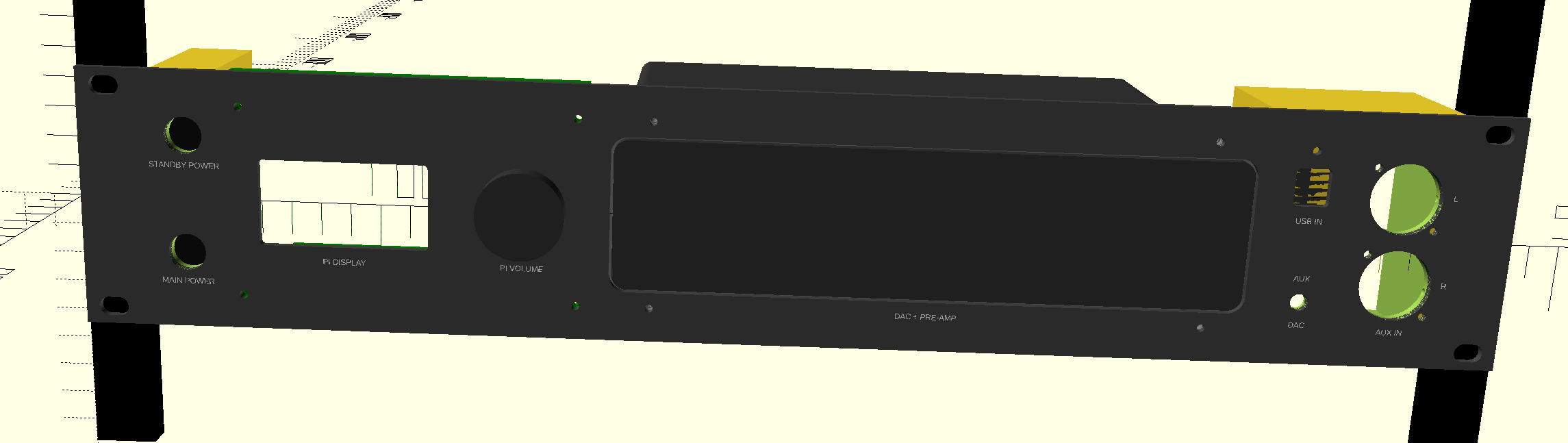
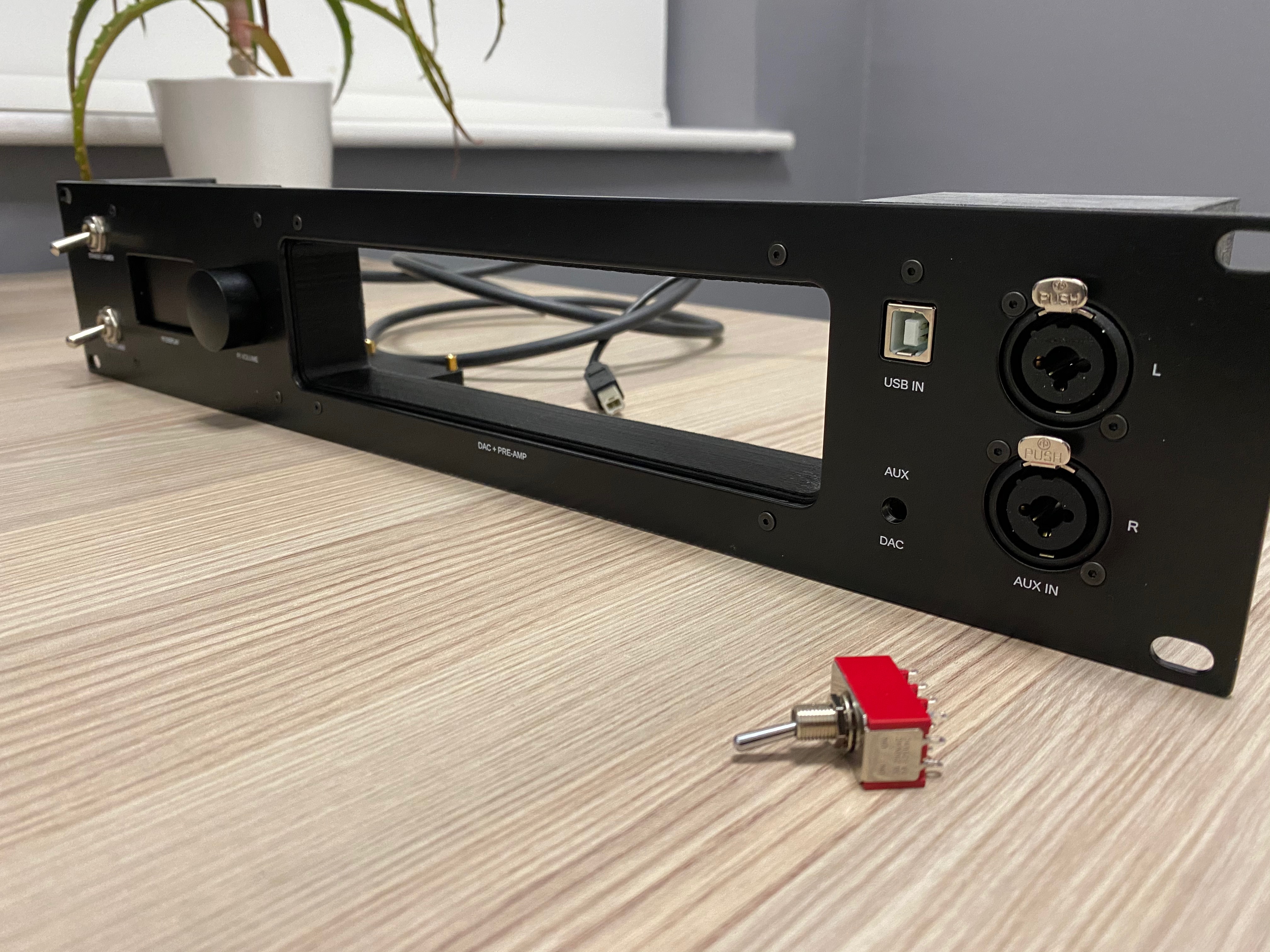
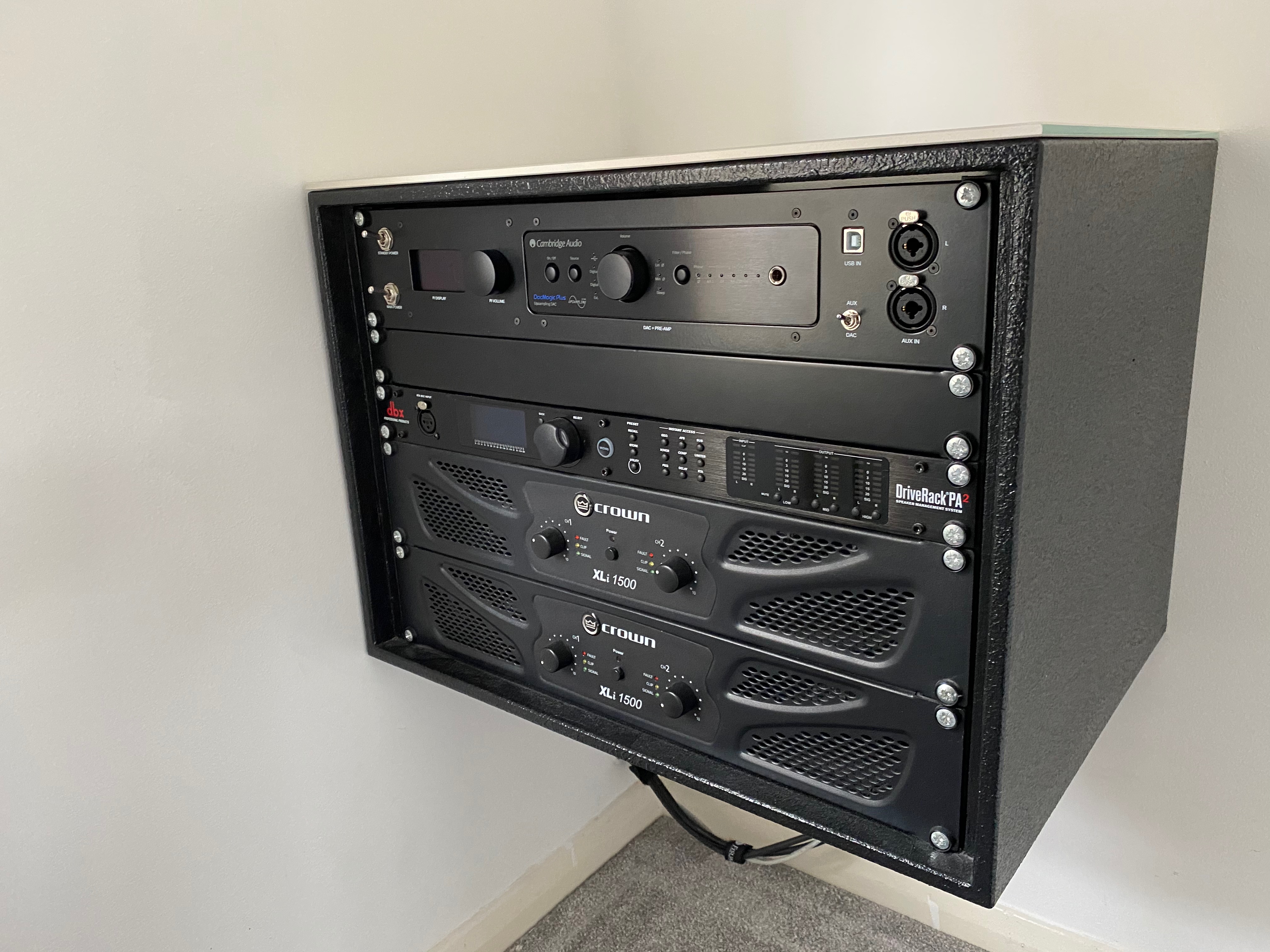
For Sheet metal
I have a HiFi setup that uses a 8U rack case with some PA amps and a 1U DSP. I wanted to add a consumer-level DAC and a HiFiBerry, together with some switches and an AUX input – but as another rack-mounted item.5 Using OpenSCAD allowed me to design the panel in 2D, whilst test-fitting and assembling in 3D.
Unfortunately, the sheet metal workshop (which has a CNC turret punch6) did not accept the DXF files directly exported by OpenSCAD. The reason was, on closer inspection, the circles (which should be arcs, DXF can handle those) were approximated as many straight lines. Worse, they were not even interconnected!

I tried a lot of different pipelines, some involving an intermediate step in SVG; but there were similar problems and even co-ordinate frame issues resulting in a flipped image and different origin.
The solution is to import the design into FreeCAD with the correct settings and export as DXF.
FreeCAD settings
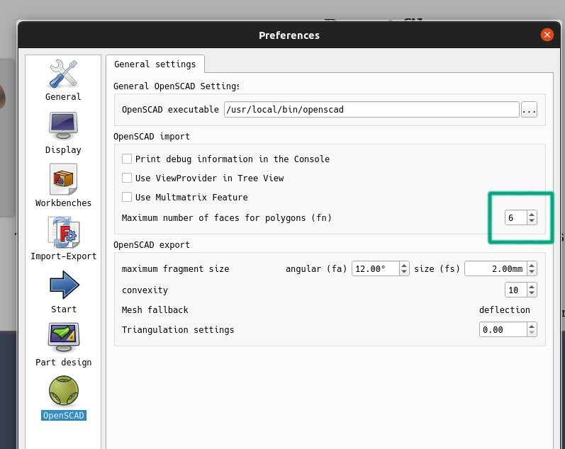
I used FreeCAD 0.19 which has built in OpenSCAD import/export support; there are some caveats though – the hull operation is not supported, and circles are apparently inferred rather than translated directly. There may be other limitations, and artefacts that result in designs that simply don’t work.
As a result of the circles being inferred, you must set a minimum number of faces for something to be considered a circle; see below.
Luckily my design was correctly imported into FreeCAD, and I was able to export a DXF with arcs to describe the holes; the turret punch software was then able to find suitable tools to finish the piece.
For 3D printing
Luckily, this is OpenSCAD’s greatest strength, in my opinion. There’s really nothing to do except increase the number of faces and possibly fix the output with a utility called ADMesh, in my experience.
ADMesh can also convert to STL binary format, which is useful to decrease the slicer loading time if you’ve automated your pipeline.
Note, however, that STL is an imprecise format – objects are described entirely as 3D polygons so curves are approximated. There’s also no standard support for multiple materials and colours. Maybe 3MF is a better choice if your slicer supports it; I think OpenSCAD can support it now but I’ve never tried it.
Honourable mention: hob3l; an intermediate slicer to produce STL files (for 3D printing) much faster.
For Milling
I’ve found it’s possible to import STL files into professional CAM software such as Fusion 360. However, I’ve noticed it can take a disproportionate length of time to create a seriously suboptimal tool-path thanks to the massive polygon count.
What can be represented simply by a STEP file can be an extremely complex approximation with STL if there are curves such as circles; this probably explains the processing time.
Somewhat fortunately, FreeCAD can import SCAD files as discussed in the sheet metal section. The same settings can be used to import 3D SCAD files, and export STEP files. Unfortunately some of my more complex designs failed to import without strange artefacts.
I’m still a bit stuck as to how to manufacture my speaker design, shown in the section about 3D rendering, as it doesn’t import correctly. I will attempt to find some DIY-affordable CAM software that can produce a decent tool-path given STLs.7
Conclusion
OpenSCAD for manufacturing
OpenSCAD is a limited but expressive and powerful CAD tool, afforded by the code-based interface. It is possible to produce complex assemblies for manufacture across many processes without too much pain – if the code is structured much like it would be in any well-written software project. It’s also possible to pre-process output to allow OpenSCAD to be used professionally in some cases.
It won’t ever replace the commercial CAD packages due to feature-set and lack of commercial support, but it is certainly preferable to me due to the version control enabled by the language; not to mention the (lack of) licencing costs and lack of cloud-based DRM.
Certain tasks such as technical drawings are out of the question without additional tools. Other things such fillets and chamfers are difficult or impossible. Rendering times can be slow, especially if many intersecting cylinders are used.
A possible alternative
Right now, I’m learning CadQuery which promises to address the shortcomings; it uses a more powerful BREP based CAD engine (OpenCASCADE) combined with the power of Python and inspiration of JQuery, of all things.
CadQuery is still in semi-early development – it started as a FreeCAD plug-in before becoming independent for the recent 2.0 release.
Most importantly, the output capability of CADQuery allows for proper STEP, SVG and DXF export, eliminating most of the problems discussed in this article.
Personally I don’t intend to stop using OpenSCAD as it’s a great tool in active development and use.
STL files are universally accepted by slicer software which convert manifold 3D shapes into G-CODE suitable for driving a printer ↩︎
Not in terms of the feature set. It will never compete with commercial CAD packages such as Fusion360 or Solidworks. ↩︎
I intend, though, to move to CADQuery, a more-powerful boundary-representation based script-only python-powered CAD package. It’s still early days but it’s showing a lot of great progress and the output functionality is better, too. ↩︎
I hope this is self-explanatory as it’s common practice with openscad ↩︎
I have a half-written blog post about this in the pipeline. ↩︎
I had no idea these machines existed! ↩︎
My friend has a DIY CNC router machine I hope to use. ↩︎
Thanks for reading! If you have comments or like this article, please post or upvote it on Hacker news, Twitter, Hackaday, Lobste.rs, Reddit and/or LinkedIn.
Please email me with any corrections or feedback.