RCDoS: cause a power cut from your phone
Moving into a new house, I felt I needed a way to test the RCDs and wiring on ring mains. It was an excellent opportunity to over-engineer something for the sake of it. What I came up with was a device, that:
- Can trip the power from a phone using a bluetooth (serial) connection
- Is powered by the mains, and therefore needs/has a UPS
- Is an awesome prank device
So far, other than surprising everyone during an unrelated countdown at a party, I detected faulty earth wiring in my new house with it. It turned out that there was a non-connection in (at least one) of the earthing points behind one of the sockets for one ring main. Fixing this, the device was then able to trip the power.

Here’s a video of it in action: https://www.youtube.com/watch?v=8_w1VXfULR4
Note that in this particular house (my old house) every circuit loses power as there is a global RCD. Some houses, including my current house, only protect the ring mains by RCD; which means the lights don’t go out – making it much less annoying/fun.
You can use picoterm on a laptop or Bluetooth SPP on an android phone. The device used is a UART (9600 baud, arbitrarily) HC-05 CY-MCU bluetooth board.
How does it work?
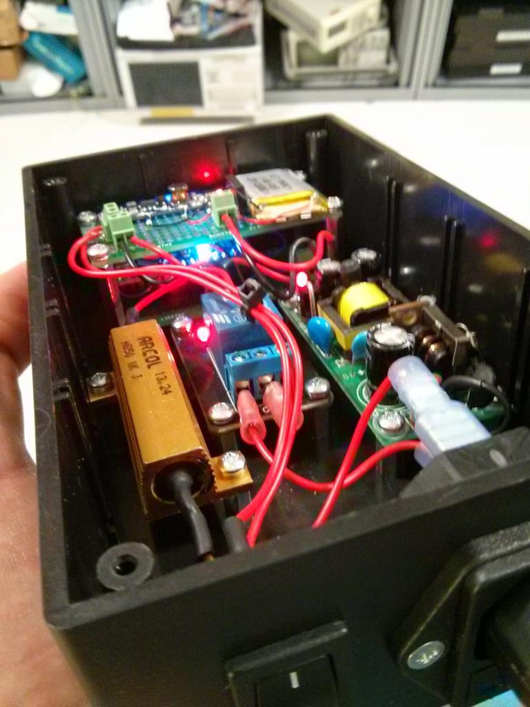
By shorting earth and live. I know that sounds explosive, and you’d be right if I didn’t use a ballast resistor to limit the current. In this case, a 2K2 resistor rated for 50W. This limits the current to around 100mA, depending on your mains voltage. 50W is overkill, considering the output is only triggered for 300ms or so. Furthermore, most RCDs are specified to trigger within something like 20ms worst case. Nonetheless, the resistor can tolerate full mains voltage over it for some time before things are a problem – using P=V^2/R the RMS dissipation is P = 250^2/2200 = 28.4W which is within the rating of the resistor, if not necessarily that of its enclosure.
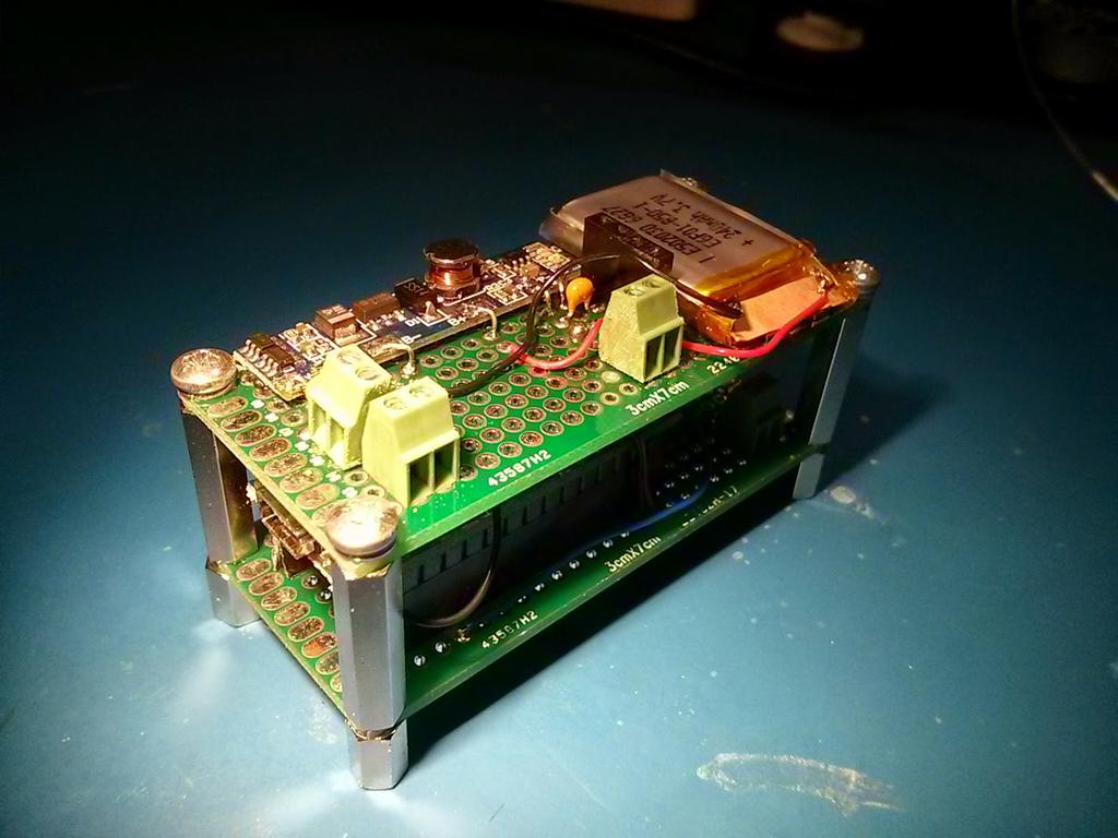
You may notice an Arduino (sorry) nano under there. You may be pleased to hear that I didn’t use the regular Arduino toolchain – instead, ino. The nano runs a real-time co-operative sheduler that I ported from ARM, originally released by tte-systems. I had previously used the scheduler to make a somewhat interesting bluetooth enabled clock.
The nano is connected to a 5v power board from dx.com. The board allows 5v charging of a 3v7 li-po cell, providing a boosted 5v output in the case of lost power. This 5v power is provided by the somewhat-OK switch-mode 5V @ 2A power supply, also from dx.com.
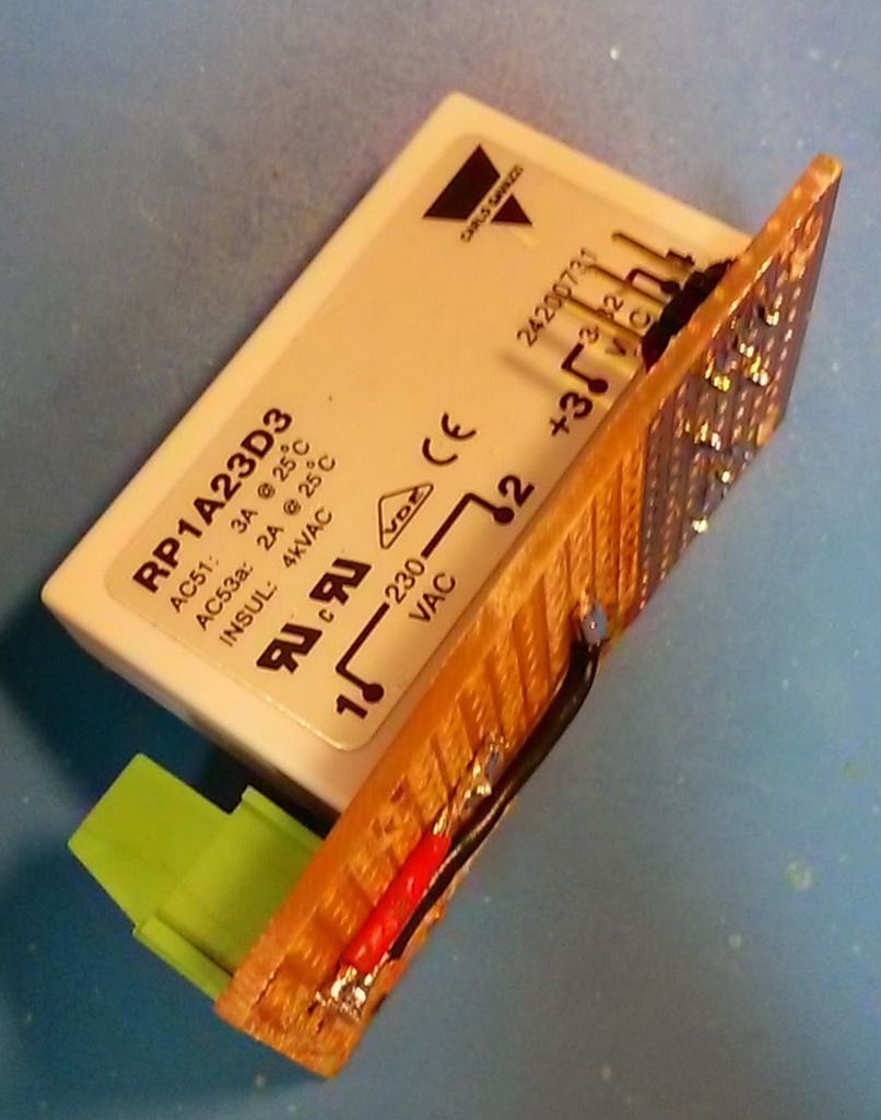
I used a mains solid state relay in the end. This was instead of the original mechanical relay which was much too loud – it would reveal its location when thrown. There was an interesting problem caused by this, however – the SSR has some inherent capacitance that is present even in the off state. Combined with the original 1K resistor, the resultant RC network was actually enough to produce a current significant enough to trip the breaker when the device was plugged in. Switching to the 2K2 resistor fixed this problem.
Here is the old version, with a mechanical relay.
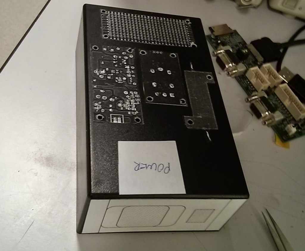
I photocopied the components and stuck them on with contact adhesive to lay out the board and drill holes. Lazy, but quick and accurate enough for polypropylene!
Bonus video: https://www.youtube.com/watch?v=2UAGolvCRvA
Thanks for reading! If you have comments or like this article, please post or upvote it on Hacker news, Twitter, Hackaday, Lobste.rs, Reddit and/or LinkedIn.
Please email me with any corrections or feedback.